Why Most Steel Problems Are Actually Drawing Problems
When steel does not fit on site — when a beam is 50 mm too long, when connection plates clash with each other, when a column sits on the wrong grid line — the cause is almost always traceable back to the drawing stage. Cedar Steel uses in-house 3D drafting to eliminate these issues before fabrication starts, supplying structural steel beams, providing steel installation and erection in Sydney, and handling commercial steel construction across NSW. Errors in the design drawings, misinterpretations in the shop drawings, dimensions that conflict between architectural and structural plans, or connection details that look correct in two dimensions but are physically impossible in three: all of these originate in the drawing and coordination process, not in the workshop.
3D structural drafting coordination is the process that catches these problems before any steel is cut. It is not a luxury feature for large projects. It is the most effective way to protect your programme on any project with more than a handful of structural members.
What Is 3D Structural Drafting and How Does It Differ From 2D?
Traditional structural steel shop drawings are produced in 2D — plan views, elevation views and section views drawn on sheets, with dimensions noted at specific points. The drafter uses judgment and experience to resolve how members connect in three-dimensional space, and issues that are not obvious from the 2D views can pass through undetected until the steel arrives on site.
3D structural drafting builds a full three-dimensional model of the structure in software. Every beam, every column, every plate and every bolt is placed in three-dimensional space at its exact position. The model can be rotated, zoomed and sectioned from any angle. Connections that appear correct in plan may reveal a clash when the model is viewed from a different direction — and that clash is visible in the computer before a single cut is made.
Cedar Steel produces 3D structural models for all projects as the basis for shop drawings and for the CNC data files that drive the robotic coping line. The 3D model is the single source of truth for the project — from the engineer’s design intent through to the machine instructions and the shop drawings.
What Types of Errors Does 3D Coordination Catch?
The most common class of error that 3D coordination catches is member clashes — where two structural members physically intersect in a way that is geometrically impossible. In a complex connection involving three or four beams meeting at a column, the two-dimensional view may show each beam connecting to the column cleanly, but the 3D model reveals that their flanges or connection plates overlap in a way that prevents both from being installed.
The second class of error is dimension conflicts. Architects and structural engineers work from related but not identical coordinate systems. A dimension on the architectural plan for a window opening may conflict with the column grid on the structural plan, leaving the steel drafter with a decision about which governs. In 2D, this decision may be made silently and not reviewed. In 3D, the conflict is visible in the model and is escalated as an RFI before steel is fabricated.
The third class is buildability issues — situations where the design is structurally correct but cannot be physically built because of access constraints. A beam that requires bolting in a location where a wrench cannot physically reach, a connection plate that blocks access to the bolt behind it, or a sequence that requires two pieces to be installed simultaneously from opposite directions — all of these are detectable in the 3D model before they become site problems.
How Are RFIs Managed in the 3D Drafting Process?
When Cedar Steel’s drafting team identifies an issue in the 3D model — a clash, a dimension conflict or a buildability problem — it is raised as a formal Request for Information (RFI) to the structural engineer. The RFI describes the problem clearly, includes a screenshot or view from the 3D model showing exactly where the issue is, and proposes a resolution for the engineer to confirm or amend.
This process is far more efficient than the alternative: a phone call from a site supervisor to the engineer describing a physical clash that nobody anticipated, while the crane stands idle and the erection crew waits for direction. RFIs resolved in the drawing office cost a fraction of RFIs resolved on site.
Cedar Steel’s project coordinator tracks open RFIs and ensures they are resolved before fabrication commences on the affected elements. On projects with tight programmes, this management of the RFI log is one of the most valuable services the fabricator provides.
What Is an Isometric Detail and When Is It Used?
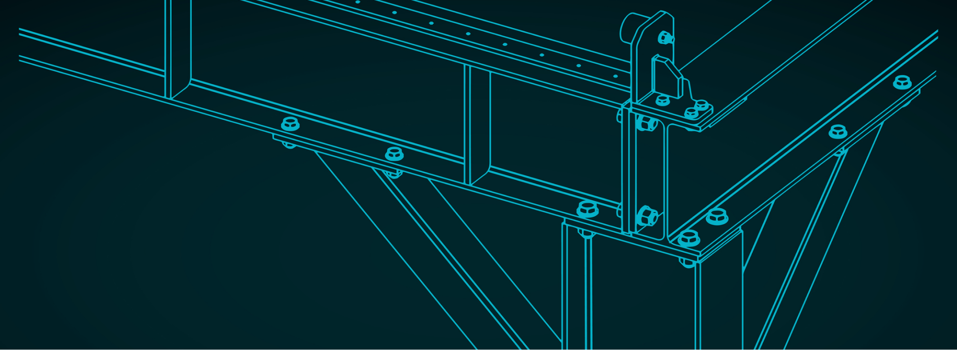
An isometric detail is a three-dimensional view of a specific connection, generated from the 3D model, that shows how multiple members connect to each other in three-dimensional space. It is included in the shop drawing set for complex connections where a standard 2D plan and elevation view is insufficient to unambiguously define the geometry.
Isometric details are particularly useful for moment connections, haunched frames, multi-way connection nodes and connections between members at angles other than 90 degrees. They eliminate ambiguity in how the connection should be assembled, reducing the risk of site interpretation errors during erection.
How Does 3D Coordination Affect Lead Times?
3D modelling takes more time upfront than producing 2D shop drawings. For large or complex projects, the modelling phase is a real component of the lead time. However, the time saved on site from fewer RFIs, fewer coordination meetings and fewer rework events almost always more than compensates for the additional drafting time.
For simple residential or straightforward commercial projects, Cedar Steel’s experienced drafting team can produce 3D models efficiently. For complex commercial, industrial or multi-storey residential projects, the 3D coordination phase is a critical programme investment that protects the downstream schedule.
Work With Cedar Steel’s In-House Drafting Team
Cedar Steel’s planning and drafting service covers 3D structural modelling, shop drawing preparation, RFI management and coordination with structural engineers for projects across Sydney and NSW. Early engagement means more time for coordination and fewer programme surprises.
Contact Cedar Steel today:
Visit: https://cedarsteel.com.au/contact/
Call: 1300 714 334
Send your drawings and we will review, assess and provide a quote within one business day. Sydney-wide from our Bankstown workshop.